Now that my project partner, Seila De Leon, and I have finished our ten week fellowship at the Yale Center for Engineering, Innovation, and Design, I will reflect on the progress we have made and the work that still exists for us. At the end of the fellowship, we had created what is, at least for now, our final prototype of the soil dryer. This dryer is one further iteration of the device we took into the field for the Western Research Fellowship Retreat in Ten Sleep, Wyoming.
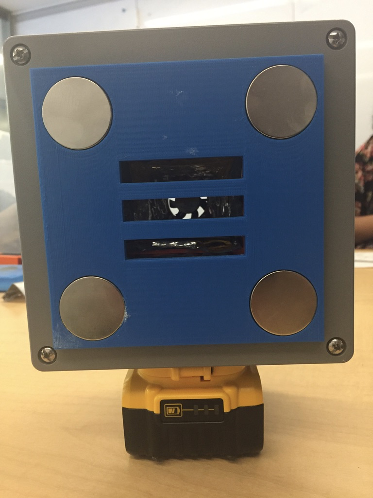
The final prototype of the summer.
The drying components listed have not changed from the prototype we took to Wyoming: two heating pads that are coded to reach a temperature of two-hundred degrees Celsius; a small 3 cm x 3 cm x 0.7 cm fan that runs for three seconds out of every ten. Additionally, the size and shape of the air chamber lined with the two heating pads have not changed. A thin aluminium plate that is 1/32 of an inch thick lays on the bottom of the chamber, and a thin aluminium bracket hangs from the top; these two pieces work in combination to create better thermal contact between the heating components and the petri dish holding the soil sample to be dried. These two components were implemented right before the Wyoming trip, and were used again in the most recent prototype because they appear to be quite effective. However, it is important to note that the LCD screen that displays the internal temperature of the chamber rarely reaches above one-hundred-eighty degrees Celsius with these added pieces. We believe that this is because the soil sample is absorbing more heat with the two aluminium pieces, which explains why the heating pads cannot get as hot, as well as why the dryer produces better results. Finally, the LCD screen and two switches that turn on the heaters and power are also the same as they were in our original prototype, as well as the one taken to Wyoming.
However, a lot of changes were made between the first and final complete prototypes of the summer. The box that encloses all internal components is now only 6” x 6” x 4”. This is less than half of the size of our original prototype made for a final project in the winter of 2017. It is also only two thirds of the size of the device taken to Wyoming. As mentioned in my last post, we wanted to make the electronics of the dryer more compact so that the dryer could be even smaller, and therefore more practical and convenient for field technicians. One of the big electrical changes made was replacing a motor driver board with dimensions 4.25” x 2.16” x 0.71” with a Tip120 transistor. This transistor has only three pins which allowed for the rather large motor driver to be replaced by a piece with an area of less than one square inch. This transistor is necessary for the function of the heating pads.
In addition to this change, the way in which the dryer is powered is much more compact with greater practicality and convenience for the field techs. As I explained in my last post, the replacement of the four 5V battery packs with one 20V drill battery would be a way to decrease the weight of the dryer, and implement a piece that field technicians already have to carry for the soil sample extractors. A few weeks ago, I was still trying to figure out if this would be possible. Now, I have implemented a drill battery into the most recent prototype and it is functioning as effectively as the previous prototype was with the four battery packs. However, this battery is only 5 amp hours, while the battery packs were 22 amp hours. This modification decreases the battery life of the running dryer from about 9 hours 3.15 hours. Despite the shortened battery life, this change is still considered to be advantageous because the drill battery is smaller and lighter and, again, a part that technicians already carry with them into the field.
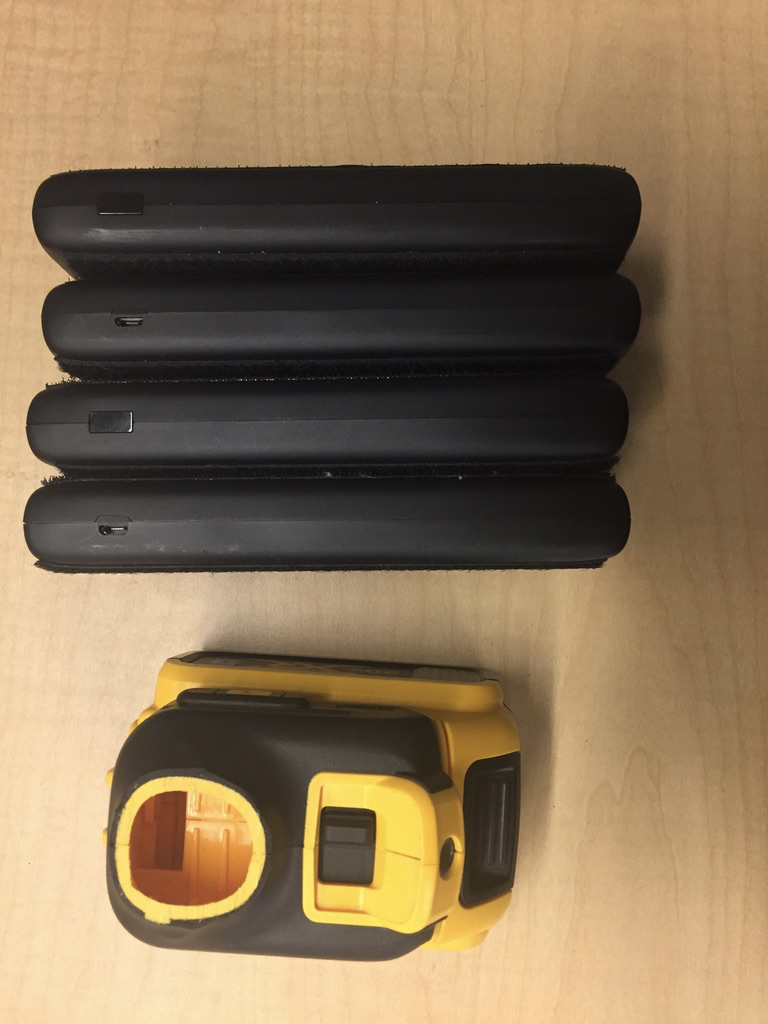
The four battery packs next to the one 20V drill battery with the sliding port from the drill handle bottom.
It is now necessary to start looking into ways to manufacture the piece from that drill handle itself that is soldered into the circuit to connect to the battery. As shown in my first blog post, in order to implement the drill battery, I had to take apart the drill, cut out the power connector from the handle, and saw off the bottom part of the handle onto which the battery mounts. This method was effective, but also very expensive because it required the complete destruction of a fully functional drill. So, I have since reached out to the DeWALT drill company to ask whether they would manufacture just the power connector and battery dock that usually sits on the bottom of a drill handle. If DeWALT is not responsive to this request, I may try to 3D print such a piece to remove the necessity of the drill part altogether.
Lastly, the substitution on the 20V drill battery for the four 5V batteries in series made it necessary to separately power the LCD screen, fan, and Sparkfun RedBoard that contains the uploaded code and controls the circuit from the heating pads. This is because previous prototypes had wires coming off at 5V for the fan, at 10V for the RedBoard and the LCD screen, and 20V for only the heating pads. This configuration is not possible when using one battery of 20 volts. Although the heating pads can take a voltage as high as 20V, these other components cannot. Therefore, the last prototype implements three 9V batteries in parallel to power everything but the heating pads. These three rechargeable batteries are mounted inside the box, but are each connected to a 9V battery connector soldered in parallel to three additional connectors attached to the charging station mounted outside of the box. This design choice was made in hopes that the box will never have to be opened by a field tech, but rather they will just have to remove the blue lid attached with magnets in order to insert a soil sample into the air chamber.
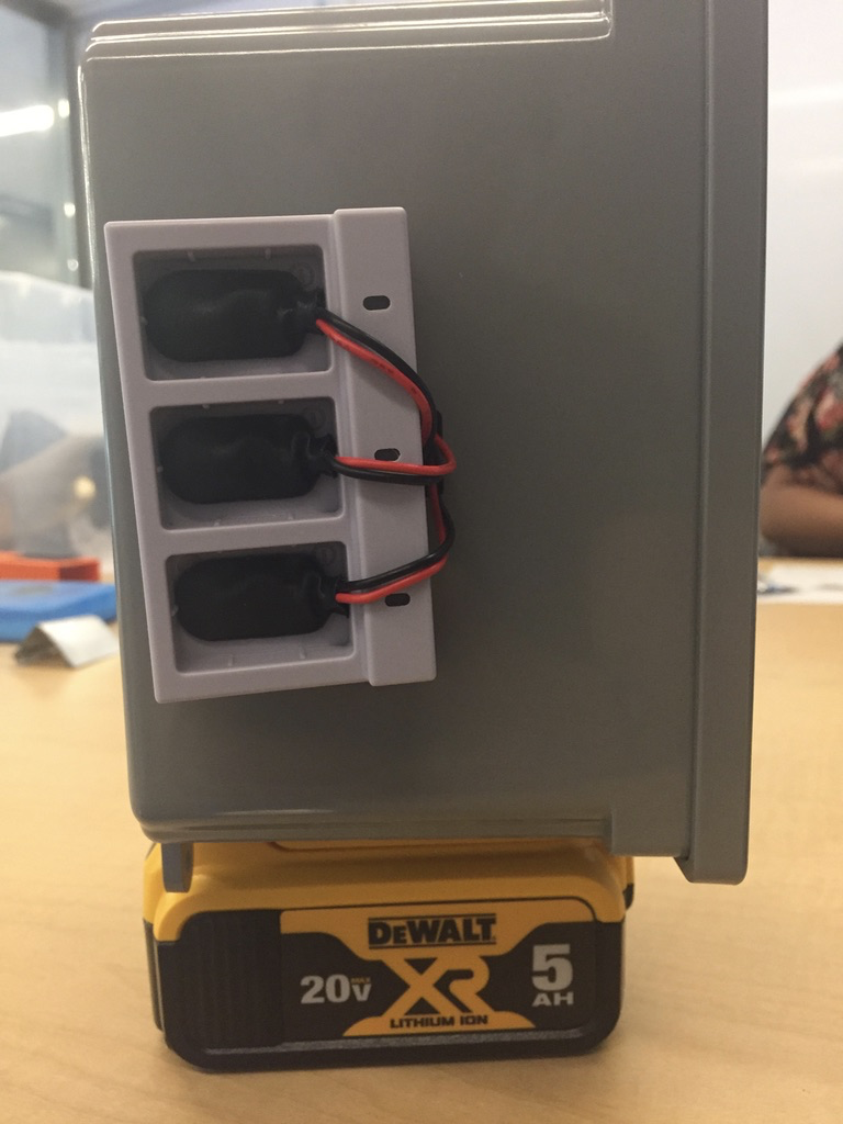
The purple charging station for the 9V batteries can recharge the batteries inside the box simply by plugging a charging cable into the side of the charging piece.
There is still a lot of work to be done on this project, but for now, Seila and I are working towards patenting or open-sourcing the functional device before continuing to make more prototypes.